

Rotogravure Printing Machine
Printing Method
Gravure printing uses an intaglio printing cylinder and prints based on a purely physical method. Gravure cylinder making begins by copper plating the surface of a metal cylinder, which is then patterned with the image. The cylinder surface is then plated with chrome to increase the printing resistance.

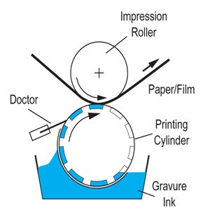
After the printing cylinder is set on the printing machine, an ink pan is used to supply the ink to the cells (image area) on the surface of the cylinder and a metal blade called a doctor is used to remove the ink from the unimaged areas of the cylinder. A rubber impression roller applies pressure to the printing cylinder to directly print the paper or plastic film. The ink used here is a quick-dry solvent type and the ink drying system relies on solvent desorption to dry the ink via evaporation.
In this way, the inks used can have a large variety of resistances because gravure printing relies on a purely physical method. Moreover, the types of printed matter (substrates)
that can be printed are also wide ranging (paper, plastic film, etc.)
Structure and Characteristics
Looking at the structure of the rotogravure printing machine, we see it consists of an unwinding unit, an infeed unit, printing units, an outfeed unit, a rewinding unit, and a drive system that rotates the rollers in each of these.
The printing unit, which is the core of the machine, consists of a printing cylinder, an impression cylinder, a doctor device, an inking system, and a drying system. By aligning
several units in the machine, multicolor printing becomes possible. Further, multicolor printing machines require a registration system between the printing units.
Classification by Application
Broadly classifying rotogravure printing machines by application, we have rotogravure printing machines for publishing and rotogravure printing machines for special applications, as shown below. Each differs in the following ways.
Rotogravure Machines for Publishing
1. Printed matter is primarily paper
2. Number of prints is large
3. Printed matter size is constant. Therefore, the printing cylinder diameter is constant
4. The printing cylinder is integrated with the shaft, so printing precision is good
5. Requires high-speed printing
6. Printing pressure is high, the machine structure is generally large, and the power requirement is large
Rotogravure Machines for Special Applications
1. Printed matter is diverse
2. Ink differs depending on the printed matter
3. Aside from paper, the printed matter is generally highly elastic and there is a limit to registration precision because of this
4. Aside from special applications, one-sided printing is common
5. Printed matter size is variable
6. Printing cylinders vary in size, so for purposes of storage, hollow cylinders (mandrel type) are common, which are somewhat less precise in terms of printing than shaft integrated cylinders
7. Aside from paper applications, printing pressure is low
Rotogravure Printing Machines for Special Applications
The rotogravure printing machines for special applications can be classified as follows.
(1) Flexible Packaging (paper, plastic film)
• paper 30 to 150 g/m2
• plastic film 9 to 60 μm
In the case of gravure packaging printing, most products use transparent film, so reverse printing, which prints the underside of the film, is typically used. As such, the printing order is black, cyan, magenta, yellow, spot color, and a finalsolid white layer. This type of 6-color printing is standard, but 8-color printing that includes two to three additional spot colors is also common. With paper, the printing order is the reverse of plastic film, or yellow, magenta, cyan, and black.
(2) Architectural Materials
• thin-sheet paper 23 g/m2, titanium paper 50 to 150 g/m2
• hard or semi-hard PVC film Hard: 0.1 to 0.3 mm thick, 0 to 15 PHR plasticizer Semi-hard: 0.1 to 0.2 mm thick, 15 to 30 PHR plasticizer
• wallpaper, standard base paper, fire-proof base paper 80 g/m2 PVC paper 220 to 330 g/m2
(3) Paperboard
• milk carton paper, cup base paper 150 to 600 g/m2
(4) Other
Basic Specifications
As mentioned above where we classified these machines by application, with flexible packaging gravure printing machines, the printed matter and dimensions vary, so the machine specifications are not uniform. The primary specification areas for flexible packaging gravure printing machines that must be determined are listed here.
1. printed matter type and thickness
2. base material width and printing width
3. minimum and maximum print repeat length (printing cylinder circumference) and printing cylinder face length
4. number of colors
5. coating weight and solvent type
6. machine speed and printing speed
7. unwinding, printing, and rewinding unit configuration
8. unwinding and rewinding system type
9. unwinding diameter and rewinding diameter
10. drying heat source
11. tension control (automatic, manual)
12. registration system (automatic, manual)
13. other attachments and accessories
14. incidentals
Printed matter ranges from polyethylene to paperboard, and although some users desire to print all types of materials on one machine, machine manufacturers see specialized machines that individually handle plastic films, such as polyethylene, polypropylene, and polyester; standard packaging paper; kraft paper; paper board; and aluminum foil, or those that handle at most two types of materials, as practical. The reason for this is that the various physical properties, including tension, printing pressure, and base material weight, for example, vary with plastic films and paper, so the structure and units are separated into light weight machines and heavy duty machines.

The printing cylinder diameter differs depending on the purpose, but the maximum diameter should be twice that of the minimum diameter to prevent the machine structure form becoming complex. Particularly when one wants to achieve a small pitch, it is better to increase the diameter of the printing cylinder and double the pitch rather than use a small diameter printing cylinder. This is because when the machine is wide and printing pressure is required for highspeed printing with a high printing precision, it is best to reduce the deflection of the printing cylinder as much as possible.
There are different types of unwinding and rewinding systems, where the operational capability of turret types is better than that of two shaft parallel types. Even so, the type of
system must be chosen based on the purpose. The unwinding and rewinding roll diameter differs depending on the printed matter, where 600 mm or less is best for plastic films
and 800-1,000 mm is required for paper. See Table 1 for base material lengths, diameters, and thicknesses.
Unit Configuration
Although rotogravure printing machines are configured by aligning the unwinding, printing, and rewinding units, the exact alignment and means of transporting the base material varies by purpose.
(1) One-sided Straight Printing
shows a good configuration that has a long paper pass length so that the ink dries well prior to rewinding. Moreover, the number of operators is reduced. When compared with Figure , however, the pass length between the final printing unit and the rewinding unit is long, so the pulling tension tends to become unstable.
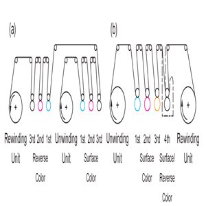
(2) Distributed One-sided Straight Printing
In this type, there are two unwinding and rewinding units, and as shown in the figure, the machine can be used for 6-color straight printing, or used to print using the units separately for combinations of 5-color and 1-color, 4-color and 2-color, or 3-color and 3-color printing. Naturally, fewer colors can also be printed.
If the combination of job details is not considered during preparatory work, the unwinding and rewinding unit installation may become unnecessary, so we must be careful. In the case of distributed printing, we must pay particular attention to tension because the paper pass length between the second unwinding unit and the printing unit is long.
(3) Double-sided (reverse-surface) Printing
In general, transparent plastic film is printed on only one side, but polyethylene tubes and heavy-duty polyethylene bags are printed on both sides. Figure 5(a) shows a configuration for 3-color surface (surface specialized) and 3-color reverse (reverse specialized) printing. With fewer than three colors, however, various combinations become possible.

In these printing units, the printing cylinder only rotates in one direction, but in some machines the cylinder can rotate in either the forward or reverse directions. The doctor unit
in this case can also be attached in the opposite direction. Although this method is used to print polyethylene tubes and heavy-duty polyethylene bags, it is also often used to print a partial adhesive coating (partial coat printing) on the reverse surface of biaxially oriented polypropylene (OPP), for example. Further, by installing a turn bar roller between the printing units in a straight printing machine, the base material can be flipped over so that the machine can be used for partial coat printing for the same purpose mentioned above. This turn bar roller is also used for paper printing.
(4) Special Configurations
In these configurations, we replace the printing unit with a coating unit, which is used as a method to print or coat for different purposes. As such, the required drying length must be set to meet the purpose. Further, in some cases, the printing unit is replaced with a flexo printing unit. In addition, the rewinding unit can be replaced with a sheeter and machines for post-printing processes.
Structural Units
Unwinding and Infeed Units
The unwinding and infeed units are controlled to continuously print in a stable manner that does not result in regstration defects, pitch defects, film meandering, wrinkles, paper breakage, or splicing loss, for example, during printing. With the rotogravure printing machine, the unwinding and infeed unit mechanical structure, application method, and calibration method have a significant impact on quality and loss rates. To maintain high printing precision, it is necessary to eliminate all tension fluctuation in the base material being fed from the unwinding and infeed units to the printing units. A brake is applied to the unwinding axle to prevent meandering, wrinkles, and sagging in the base material, which means tension is required to draw the base material. If the strength of braking is constant, tension will increase as the base material diameter decreases. Further, when splicing in a new base material, there is a momentary tension increase over the reference tension. In this way, a large tension change occurs as a result of changes in base material roll diameter and base material splicing, so the unwinding unit typically has some sort of tension calibration device. These devices include the unwinding brake system and infeed unit. These devices detect the tension, which is fed back to the unwinding brake and infeed rollers in an attempt to reduce tension fluctuation.
Here, let us look at the unwinding unit and infeed roller nit along with a tension control method and machine structure that has been used until now.
Unwinding Axle
There are several methods for attaching base materials of paper and plastic film, for example, to the shaft, including the tapered cone locking method, expansion method, and
shaftless method.
(1) Tapered Cone Locking Method
For the most part, the base material paper or plastic film is wound around a paper core, which generally has an inside diameter of 76 mm and an external diameter of 92 mm (called a 3 inch paper core). Here, tapered cones on either end of the unwinding shaft are used to lock the base material from either side of the paper core. One end of the unwinding axle has a braking mechanism (mechanical band brake, magnetic powder brake, etc.) and
a gear that interlocks with the brake, and the other end of the axle has a groove for a side lay arm used to adjust the axial direction position.
(2) Expansion Method
This method first inserts the unwinding axle into the paper core, after which air pressure is applied to the inside of the axle to force out protrusions that lock the axle to the paper core. This method allows for rapid removal of the base material from the axle and for easy centering of the paper core, but has problems with the base material tending to rotate in
an eccentric manner.
(3) Shaftless Method
To ease the replacement of the base material, a two arm turret method is used for the unwinding and rewinding units. To further speed up and ease replacement, a shaftless
method is used to mount the base material. In this method, the paper core is locked in place using the pressing pressure of an air cylinder. Conventionally, it is necessary to prepare several tapered cones and replace these when the width of the base material changes. Recently, however, with greater importance being place on operability, methods that increase the stroke of the spindle shaft on the operation and drive sides, or methods that shift each of the turret arms on the operation and drive sides eliminate the need to replace the tapered cones, which increases the widths of base materials that can be used.
Further, the shaftless air chuck method produces little base material eccentricity and provides stable tension. In flexible package gravure printing, there is a diversifying range of base films, while low tension unwinding is required for thin OPP, CPP, PET, and nylon, in particular. As such, the bearing unit of each unwinding shaft must have a structure that rotates smoothly at low-torque or the plastic film will stretch and tension will tend to become unstable. In addition, the automatic tension controller will also fail to operate
effectively.
Next, let us show the basic equation for tension during stable operation: T0=(τE+τM)/R(1)
T0: tension (N), R: unwinding roll radius (m), τE: external braking torque (N·m), τM: braking torque as a result of mechanical loss (N·m).
As we see from Equation 1, the bearing unit must rotate at low-torque. With shaftless unwinding, there is a lower limit to tension.
In this case, we use an auxiliary drive (mechanical loss cancellation) to reduce mechanical loss and maintain lowtension by combining this with a magnetic powder brake. Further, this auxiliary drive motor is also used as a pre-drive.
In addition, some machines connect a DC motor or AC vector motor to the individual unwinding shafts as unwinding unit tension control, while other methods combine control with a base material pre-drive during automatic splicing, both of which are common methods.
Unwinding Unit
The unwinding machine must be equipped with a set of bearings to support the unwinding shaft, an adjustable brake, and a side lay arm system that can adjust the axial direction.
Carriage Method
In this method, generally, the bearing, brake, and side lay arm units are set on a wheeled carriage; some types are loaded with the roll outside of the machine and pulled into the machine afterwards. This carriage method is rarely seen in gravure printing machines, but is often used in coaters and laminators. In many cases, the method is combined with a turret system and equipped with an EPC system that automatically controls the edge position of the material.
Fixed Method
This unwinding unit is equipped with the bearing, brake, and side lay arm units, so if the job requires only one base material roll to complete the printing, one set is sufficient. In the case of long run printing, however, a consecutive two axle parallel method equipped with two sets of units above or across from each other, or a two level mounting system is
used to speed up the replacement of the base material and ease splicing.
Turret Method
To further ease the exchange of the base material, a rotating unwinding device with two or three arms is used, called a turret. Large scale rotogravure printing machines for publishing use three arm devices, whereas flexible packaging machines commonly use a two arm device. In most cases, turret rotation uses an electrical drive.
Given space restrictions we will continue this topic in a following issue, beginning with unwinding brake and tension control.