

Imagine the steel rule diecutting world without perforation rule. Since we are all becoming more intellectually expert at steel rules for diecutting (it has been my pleasure to unofficially qualify the readers of my two previous steel rule articles in The Cutting Edge magazine as experts), it hardly seems possible to think of our world without perf (perforating rule).
Let’s begin with what perforation rule is (see Diagram 1). By definition, to perforate is to make a hole or holes in something. In the diecutting world, we use many variations of perforation blades. In general they cut and then skip cut. The various ways in which this is employed will be discussed in detail later, but for right now, let’s start with what perf was intended to do.
Perf was introduced at first to be a better, more clean and accurate way to fold. Since the beginning, this interesting application of cut and space rule has evolved into – at least from my count – four functional attributes, two standard applications, two feature applications and five ways to specify the perf. Obviously, this drives the steel rule manufacturers utterly buggy or – as I used to say when I worked for one – the challenge will make us stronger. (This is where a texter would put in a smiley face symbol.)
Functional attributes for perf include fold, reverse fold, fold and tear and tear. Perf and Perf score are its standard applications. Its feature applications include slit and crease, and ‘cut and cut.’ Perf has five specification choices namely, balanced where cut segments and gap segments are equal; unbalanced where the cut segments and gap segments are unequal; randomized where cut segments and gap segments are unequal and random; serrated where serrated rule has teeth; and lastly, non-serrated where non-serrated rule is straight edged (no teeth).
Fold
We all know that folding is crucial to any package design. This is true for folding cartons, corrugated, pocket folders and even non-paper-based products that are diecut and folded. In most designs, denting or purposely deforming the material so it can precisely bend creates a fold. The bend can range from 0º to 180º. Yes 0º! Some cartons are creased with an ‘X’ pattern to control warp and add rigidity (like a piece of tin duct work), but that is a different topic.
Today, with a great deal of mechanical automation in carton/case erection, loading and gluing, the fold accuracy, force to bend and folding reliability become paramount. Perfis amore reliable fold than crease. A diecut perforation is basically a cut and space (or crease) pattern. When a material is cut, the result is a precisely placed weak point. When the weak points are lined up, the result is an accurate fold line.
A common scenario when perf is used instead of crease for a folding application is when trying to fold corrugated in a parallel direction to the flute structure. This is far from reliable without matrix or counter creasing. A good example would be when two fold lines are close together(like railroad tracks) and they each need to end up at 90º (see Diagram 2).With crease on corrugated, this is highly unlikely. One crease line will be weaker than the other, depending on where the flute assembly is struck. A roll over will result when the weaker of the two crease lines gives way to the neighboring fold that is more resistant. With perf, both fold lines are identical in resistance to fold, so they will fold exactly along the cut segments and this basically eliminates the flute structure as a factor.
When discussing folds, the major arguments against perforation are the cosmetic look on the outside of the finished product, the potential loss in structural integrity and rule cost. Perforation rule is slightly more expensive than crease. Barring these arguments, perforation for a fold is definitely superior and more reliable than the crease.
Reverse fold
 One advantage perf has over crease is that the fold line is bi-directional. Creases generally fold inward toward the side they were struck from. Perforation does not care which way it ultimately gets folded. This is advantageous for inner parts and tapering the opening of a glued and erected box by allowing the flaps to fold backward slightly.
When you get a product that has inner packing to hold a part in place or protect it from damage, most often you’ll find perforating rules in action folding backwards. We simply could not make these packages without perf.
Fold and tear
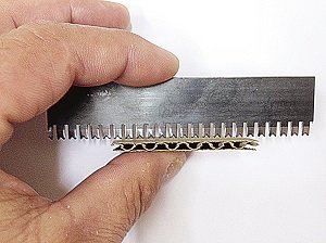
Fold and tear is self-explanatory, but much easier said than done. This is true for paper, carton and corrugated. It is best if you consider the reliability of the process of tearing in that order as well. What I mean is, paper is a single layer of substrate, carton stock is multiple layers compressed into one mass and corrugated is multiple layers of single sheets. To complicate things, with corrugated the sheets are spaced apart, connected at the flute tips and these connection locations alternate positions. The material does not respond in a reliable way (see Diagram 4). For single wall fluted corrugated, the perforation is cutting in one of three ways – through paper liner, then two liners glued together; through two liners glued together, then through a single paper layer; or through three individual, independent and unattached sheets of paper. This is compounded with double wall and triple wall. Additionally, most corrugated board doesn’t incorporate the same quality or grade of paper liners in the combined product. Each paper liner has a specific fiber length and arrangement and consequently, this equates to the tearing characteristics.
All hope is not lost! It is important to understand the variables in order to define the limitations and from this adopt reasonable expectations. Tear and fold perforations are getting better and more dependable as the perforations are refined and tuned more reliably to the substrate. Constant evaluation and study of the substrates and how they react combined with better controls on the diecutting process and other controllable variables, like humidity and paper making, will afford the continued improvement of the results.
Fold and tear applications should be thought of as tear applications that need more holding strength or resistance to tear. How far the fold will be taken and whether it will be running with or across the flutes or grain should also be taken into consideration. By setting different parameters for each of these conditions, you can get a pretty reliable system.
Guidelines to follow

Folding to 90º requires more strength (resistance to tear) than if you don’t fold it at all, but folding it to 180º requires even more strength because the fight of the material and the needed stretch of the nicks (uncut perf areas) before they break.
Similarly, folds running across (perpendicular)to the flutes will also require more strength (see Diagram 5). Just bisecting the flute structure across the rigid flutes makes the tear very easy.
When you add the stress of folding, you need to compensate for the already weakened condition. Think of it this way – when the perfruns with the flutes, the fold and tear is flimsy and after the inner and outer liners break, the fluted medium stretches and adds resistance when bending/tearing. When the perf crosses the flutes, there’s no flimsy stretch about it.
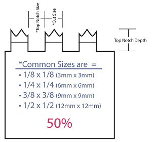
 Evaluate the space to cut ratio and build a system based on percentages. This can be done with any perf. For instance, a 0.25 x 0.25-inch (6 x 6 mm) perf equals 50% cut and 50% uncut. This is a 50% hold. Once you have this, adjustments can be made to increase or decrease the holding power. The formula is: space ÷ (cut + space) = % of hold.
To plan a system to take tear-perf to folding, use the following. If tearing equals 18% hold to cut ratio on a 1 inch (25.4 mm) perf, 0.18 inch (4.57 mm) is uncut and 0.82″ (20.8 mm) is cut.
If you want to fold and tear with the flutes to 90º, you need to go higher in percent than what you’re tearing at. The tear strength of 18% would go to around 24% and if you want to make a bend of 180%, maybe go to 30% hold. It’s all relative, but can definitely be managed.
You can find a lot of these guidelines on National Steel Rule Co.’s website, www.steelrule. com, under PERFormaX. Other steel rule vendors are also a good source for this information.
Tear using perf
Tearing with perforating rule is also becoming more dominant in the packaging field. Many packages use a product referred to as zipper rule. This is a product that takes cutting rule and forms various shapes with the cutting edge to achieve cut segments separated by small gaps. The most common shape looks like a hockey stick. You’ll find this used commonly on postal packages an dice cream cartons (see Diagram 6). However, straight-line perf in an unbalanced or random cut notch style are also today’s fads.
It is recommended to follow the cut to gap ratio for these. The higher the cut percentage and the smaller the gaps are, the less resistant the perfline is and the better the finished tear looks. The trick is finding an adequate amount of hold to make it through packing and logistics while maintaining a reasonably good look after tearing.
Perf
Perf is simply a cut and gap rule that has the gap notch made to a depth that during diecutting will not touch the substrate. Well, in some cases it may contact the substrate, but it is not intended to crease.
Perf score
Perf score is a cut and gap rule where the gap notch is at a specific depth. The rule manufacture makes perf score to order, so you need to specify the crease height when ordering.
Radius combo perf score
When perf is notched to remove the cut portion, the punching process leaves the created crease portion straight and sharp (seeDiagram7).Secondary processes do a decent job of breaking the sharp edge with buffers and wire wheels. However, the Radius Gullet Combo product is fashioned by a follow up process that physically impacts the sharp edges and makes them even better.
Slit and crease
Slit and crease is a combination perfthat is intended to have the cut portion of the perf stop short of cutting completely through the substrate. The gap space is intended to crease. The trick here is planning. The cut height must be lower than the rest of the cutting rule where we do want complete cutting. The crease portion must help with this. The crease compresses the material and holds it. If the cut portions are planned correctly, they can not reach far enough to cut through.
Cut and cut
Cut and cutis a product designed to have part of the perf cut through and a lower cutting portion that does not cut through. Of course, this cannot be done on a rotary and must be done on a steel to steel, flat bed machine. Counters can be engineered to help with this.
Same height cut crease
 Same height cut crease is also used only on the flat bed and must have a counter. The reality is the rule is not exactly the same height. The cut portion is a few thousandths of an inch (approx. 0.0762 mm) lower. Transitioning from the cut to the crease can cause some material fight at the intersection. Some diemakers deal with this using the counter plate and others nick the rule at the intersection between cut and crease.
So now you are an expert on perforation rules! In summary, the style and variety of perfrules are endless for their application. Many designers use perf to add value or achieve a unique characteristic for their package. Perf rule is straight forward and very specific, but a good understanding of the options will help you to best solve your individual packaging
challenge with folding, tearing and who knows what else!
(Editor’s note: This is the third article in a series on how to better understand steelrule for diecutting, including why rules are different and how to apply them.) (Kevin Koelsch is vice president–operations for Dynamic Dies, Inc. He may be reached at 1-419-865-0249 or by email at kevin_k@dynamicdies.com. For more information, visit www.dynamicdies.com.)
(This article is reprinted with permission from the International Association of Diecutting and Diemaking’s monthly magazine, The Cutting Edge, October 2013.)
The IADD is an international trade association serving diecutters, diemakers and industry suppliers worldwide. IADD provides conferences, educational and training programmes, a
monthly magazine, online resource library of 500+ technical articles, industry experts to answertechnical questions, publications and training manuals, recommended specifications,
online used equipment marketplace, videos and more. IADD also co-presents Odyssey, a bi-annual trade show and innovative concept in technical training featuring, a hands-on Techshop where training programmes come alive in an actual working diemaking and diecutting facility inside the exhibit area. Visit www.iadd.org or call 1-815-455-7519 for more information.